Release status: digital prototype, not a validated functioning hardware kit.The CAD meshes and digital articulation are delivered. Motor fit, mating interfaces, fastener access, cable routing, load capacity, full-range self-collision, electrical design and supplier acceptance still require work. Some interfaces may need geometry changes after dry assembly. No payload, precision, lifetime or autonomous capability is certified. Do not order a full kit or energize an assembled arm from this revision alone.
Start here
- Explore digitally. Open AURA SIX on Ovvilo, or open
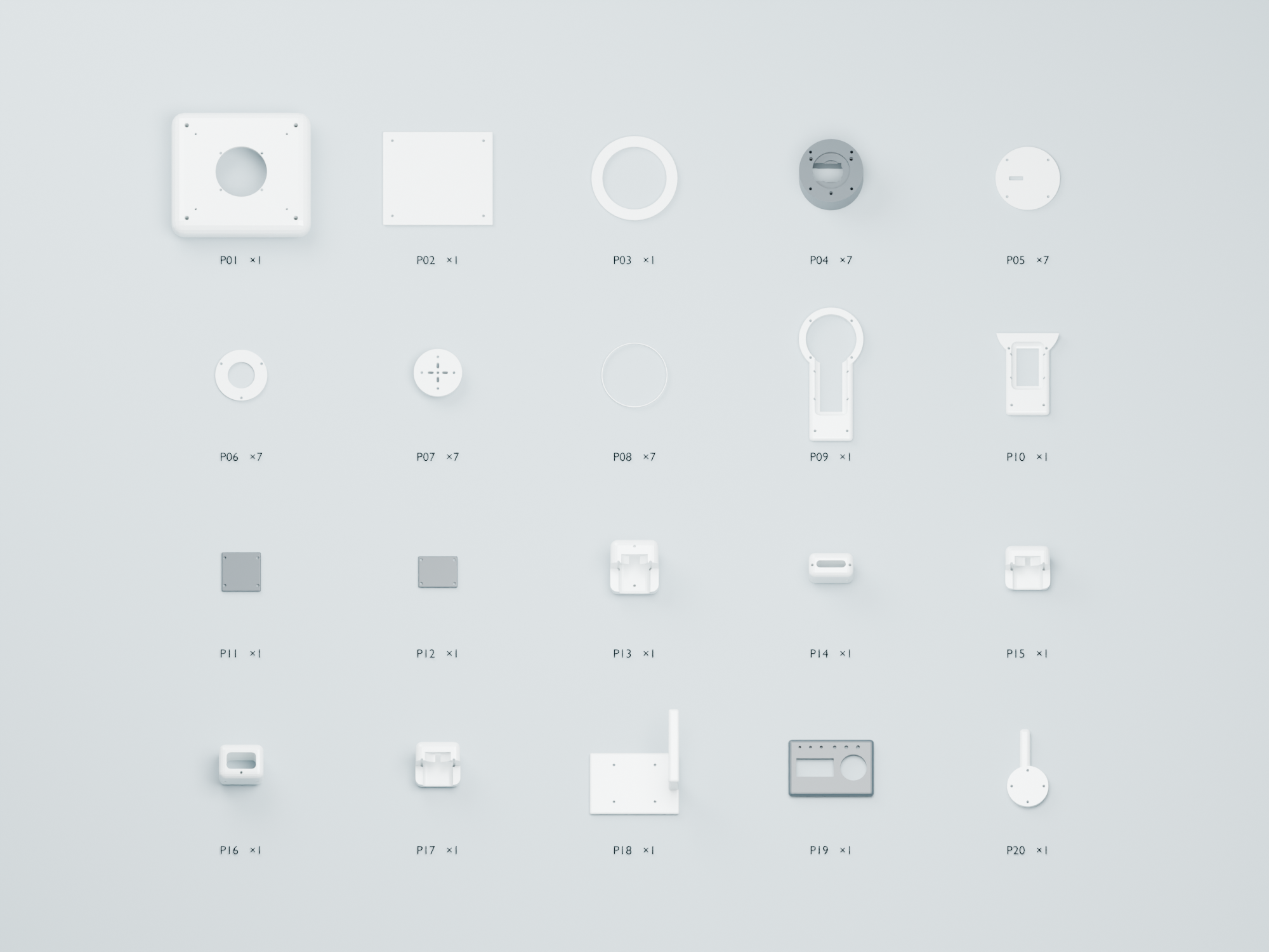
OVVILO-AURA-SIX.blend in Blender. Select J1–J7 and rotate about local Z. Play frames 1–200 for the coordinated motion study. Scene 02 contains the labeled part atlas. - Read the qualification notes. The purchased-part BOM identifies the mechanical and electrical decisions still open. Mesh validity alone does not establish assembly fit or strength.
- Print only P19 first. Measure the chosen servo and inserts, then compare with the fit gauge. Record material, supplier, orientation, measured dimensions and fit. Update the parameters before the remaining prototype prints.
What makes this design different
Serviceable modules
Seven repeated servo cartridges, individual rear covers, bearing retainers and replaceable output flanges reduce the number of unique service parts. Color bands identify the joints. The link troughs provide accessible spaces for a future qualified cable route.
Expressive articulation
Base orbit, shoulder lift and elbow sweep position the arm. Forearm roll, wrist tilt and tool roll orient the end. A separate angular gripper opens one moving finger against a fixed finger. The browser animation coordinates these axes; it is not physical collision simulation.
Futuristic form, conventional mechanics
The design uses pale shells, dark joint housings and coral datum bands. The orbital appearance is an aesthetic interpretation of futuristic technology. No quantum processor, quantum actuation, magnetic levitation or unusual material capability is claimed.
A clear learning path
Start with the offline kinematic tools, qualify a single joint, then integrate physical control. Vision, teach-and-repeat and learned manipulation are development paths; they are not installed capabilities of A0.
Reference review and research
The VEILINK listing describes six arm degrees of freedom, a separate gripper, seven STS3215 C001 servos, internal wiring and interchangeable tools. These are useful baseline features, not claimed inventions of AURA SIX. Its author also supplies assembly and kinematic resources in the project repository. No VEILINK CAD, code, images or assembly drawings are redistributed here. AURA geometry and software were created independently.
Hugging Face’s SO-101 guide informed the emphasis on identifying motors individually, calibrating each unit and keeping assembly approachable. Bring Your Own Hardware explains the custom robot interface required for an arm with this geometry. AURA is not a drop-in SO-101 profile. SmolVLA suggests a future camera-and-language learning path, but would require an implemented hardware adapter, matching action conventions, recorded data and task evaluation.
The Waveshare ST3215 product listing distinguishes voltage/torque variants. It does not provide a validated continuous torque rating for this assembly. Lock a specific servo drawing and voltage before sourcing. The Slant platform documentation confirms platforms organize files, orders and webhook notifications. Ovvilo’s existing platform should be reused.
Printable parts
20 unique designs / 50 printed pieces, including one fit gauge. Each STL is centered on its own plate with minimum Z = 0, in millimetres. Do not scale to inches. STL files contain one part design each; quantities are in the BOM. The atlas is a visual inventory, not a combined production plate.
Manufacturing intent for Slant 3D
PETG is the requested starting material for the prototype parts; live availability and suitability must be checked. Render colors and finish are illustrative. Grip pads are purchased silicone. The files fit Ovvilo’s configured 220 × 220 × 220 mm per-part limit and pass its existing supplier-file validator, but they have not been submitted to or approved by Slant.
Print orientation matters. Start broad flat parts on their broad face; print cartridge rear opening up only after a slicer confirms bearing-seat support and accuracy. Upright journals favor circularity. Orthogonal brackets and the fixed finger require explicit orientation/support review. Slant’s process must qualify support removal, bearing-seat finish and insert placement. Do not assume the API offers custom wall count, infill or orientation overrides.
A useful engineering trial is a 0.2 mm layer, 0.4 mm nozzle, five perimeters and local solid regions around inserts and bearing seats, if the supplier can support those requirements. These are trial settings, not an approved supplier profile. Inspect thin slot walls and small bands. Deburr and measure every bearing pocket; do not force a bearing into a split or distorted print.
Fulfillment boundary. Slant printing does not imply supply of motors, electronics, bearings, pads, assembly or calibration. The supplier manifest lists every printed item and quantity, but has no invented file IDs or quote. Ovvilo’s present multipart checkout caps products at 10 distinct parts. This 20-part package needs an explicit product-flow extension and complete quote validation before full-kit checkout. The prototype page therefore provides files without a Buy button.
Assembly development sequence
- Qualify P19 and the motor. Check actual body length/width, output-shaft location, connector clearance, horn diameter and pattern. The nominal cavity is 42 × 21.2 mm with a provisional offset. A body fitting the opening does not establish shaft alignment.
- Build one unpowered cartridge. P04 holds the motor envelope; P05 closes the rear; H03 fits the front seat; P06 retains its outer race; P07 runs inside the bearing and bolts to the metal horn. Check that the journal rotates without binding and that screws neither bottom out nor strike the rotor. Bearing fits, shims and axial retention require measurement.
- Resolve the fastening stack. Use P04’s M3 insert pockets only after selecting and testing the insert. Retainer screw heads must be at most 1.8 mm tall. Tie bolts need sufficient nut engagement without hitting cables. Determine actual screw lengths on the first cartridge and record them in the BOM.
- Dry-assemble the base and links. P01–P03 form the plinth; P13 carries the shoulder; P09/P11 and P10/P12 are the link bodies and covers. Confirm every fixed housing-to-link interface and accessible bolt path. Several orthogonal bracket connections remain provisional in A0; revise them before powered assembly rather than relying on glue or visual overlap.
- Dry-assemble the wrist. P14–P17 establish the change of axis between cartridges. Check rotation by hand at small increments, with the arm supported. Verify every bearing, housing and moving cover has clearance over the intended working envelope.
- Fit the gripper. P18 is the stationary outboard bracket and P20 is the moving finger. Add the two silicone pads. Check contact alignment, pad retention, closing gap and finger sweep. Angular jaws have changing contact geometry; no constant grip force or parallel-jaw behavior is claimed.
- Design the cable and power system. Route cables with slack loops and strain relief; use hard rotation limits so wires do not twist continuously. Establish supply, fuse, connector and disconnect ratings from the selected hardware. A torque-off command is not a physical emergency stop and may let the arm fall.
- Commission only after qualification. Bolt the arm to a rigid surface. With the links supported, assign servo IDs one at a time, determine actual zero positions and directions, and validate small low-speed motions. The included software never energizes motors. Physical control integration is a separate unfinished engineering step.
Joint conventions and motion software
Blender and the kinematic manifest use right-handed coordinates, millimetres and local-Z revolute joints. A fixed XYZ rotation and translation precede each joint rotation. The exported glTF uses Y-up coordinates, so the website applies each joint rotation about local Y. These representations were numerically cross-checked.
These are display limits, not measured hardware-safe limits. The provisional tool datum is (20, −16, 120) mm in the J6 frame and must be replaced by a physically calibrated TCP. The gripper angle does not change this fixed reference datum.
aura-six-software/aura_motion.py provides forward kinematics, position-only damped inverse kinematics, and synchronized quintic trajectories. It requires NumPy. Running it writes an offline CSV; it contains no serial driver, hardware connection or autonomous policy. The inverse solver leaves orientation unconstrained and reports failure when it cannot converge. Neither it nor the viewer checks collisions.
The demonstration trajectory uses a 15°/s speed bound and a 30°/s² acceleration bound. Quintic easing has zero endpoint velocity and acceleration. aura-six-kinematic.urdf reproduces the joint transforms with frame markers; it intentionally has zero effort limits and no dynamics or collision model.
Load and power: decisions still open
The 100 g payload is an aspiration, not an available product rating. Wrist mass and link self-weight can dominate the shoulder load. For example, an assumed 0.8 kg of distal assembly centered 0.18 m from the shoulder plus 0.1 kg at 0.34 m creates approximately 9.81 × (0.8 × 0.18 + 0.1 × 0.34) = 1.75 N·m before acceleration, friction or safety margin. Those masses are illustrative and must be replaced by measured/sliced masses and actual centers of mass.
A candidate 30 kg·cm servo’s advertised stall figure corresponds to about 2.94 N·m, not a sustainable working torque. A notional 30% stall screening allowance is only 0.88 N·m, which fails the illustrative 1.75 N·m load case. That fraction is an engineering screening assumption, not a vendor continuous rating. The first hardware revision may therefore need shorter links, lighter wrist actuators, counterbalancing or reduction gearing. None of those upgrades is implemented or qualified in A0. Do not extrapolate a safe payload from the animation.
Power requirements cannot be finalized by adding nominal idle currents. Check simultaneous moving/stall currents, controller traces, wiring, connectors, fuse behavior and recovery after brownout. Use the exact servo voltage and a physical motor-power disconnect. Thermal soak, endurance and loss-of-power tests remain required.
Sampled interface audit
After revising the elbow opening, wrist spacing, adapter locations and rotating-journal clearances, 41 sampled frames returned zero cross-link triangle-surface intersection candidates. This test covers the Blender demonstration animation only. It excludes contacts within a rigid assembly, purchased hardware, complete containment and manufacturing tolerances; it is not a full swept-volume or physical fit certificate. See the detailed interface audit.
Validation record
Passed digitally
- 20 STL files: finite coordinates, consistent binary structure, no zero-area triangles, one connected component, two faces per edge, positive signed volume, minimum Z = 0.
- All part bounding boxes fit the configured 220 mm limit and the existing Ovvilo STL validator.
- 31 poses: exported model joint origins agree with independent kinematics within 0.001 mm.
- Three nearby inverse-kinematic targets converge with less than 0.05 mm residual in the mathematical model.
- Example trajectory stays within configured speed and acceleration bounds; invalid angles and an unreachable target are rejected.
Still required
- Motor drawing lock, pilot part, complete mating interfaces and fastener schedule.
- Self-collision, cable bend and travel-envelope validation.
- Supplier material/process acceptance, slice review and actual quote.
- Static, fatigue, creep, heat and dynamic load tests.
- Power design, emergency-stop implementation and physical controller.
- Full multipart checkout integration and hardware-kit fulfillment.
- LeRobot adapter, data collection and task-specific AI evaluation.
Files and provenance
The package contains the Blender assembly, glTF model, 20 STLs, print and purchased-part BOMs, part manifest, supplier preparation manifest, numerical validation report, motion software, kinematic URDF, this guide and two renders. The parametric Blender generator is included for revision. Original local sources are credited above; no third-party mesh or model weight is bundled.
This is a reviewable first design revision. Completing a reliable beginner product requires the outstanding engineering and physical tests, with changes fed back into the CAD and guide.
OVVILO AURA SIX · A0 · September 2026